
Controlling a motor with an Arduino is relatively easy. In addition to simply spinning the motor, you can control the position of the motor shaft if the motor has a rotary encoder.
Faraday's Law states that:
Any change in the magnetic environment of a coil of wire will cause a voltage (emf) to be “induced” in the coil.
This explains how generators are able to produce voltage. This is mechanical energy to electrical energy conversion. Motors operate in reverse of generators; they convert electrical energy to mechanical energy. In motors, current is fed into the armature winding which creates a magnetic field that interacts with the magnetic field created by permanent magnets in the stator. The interaction between two magnetic fields causes the armature to rotate.
There are many different types of motors, including:
Direct Current (DC) motors (the one that I'll be using in this tutorial).
Alternating Current (AC) motors.
Brushless DC (BLDC) motors.
Brushless AC (BLAC) motors.
A rotary encoder is a device that converts the angular position or motion of a shaft or an axle to an analog or digital code. There are two types of rotatory encoders:
Incremental encoders. An incremental rotary encoder outputs pulses only while a motor is rotating. To determine the shaft position using an incremental encoder, you must know the starting position and the use external circuitry to count the number of output pulses.
Absolute encoders. An absolute rotary encoder outputs a digital code corresponding to the rotation angle. There is no need to count pulses to know the position of the motor shaft. You need only read the digital output of the encoder.
In this project, we are using an incremental rotary encoder. The figure below shows a typical rotary encoder.

An H-Bridge is an electronic circuit that enables a microcontroller, such as an Arduino, to control the movement of a motor. A microcontroller cannot be connected directly to a DC motor because the microcontroller cannot supply the high current required by the motor. The H-bridge contains the high-current switches needed for motor control. These switches are controlled by signals from the Arduino.
An H-bridge allows a motor to be moved forwards or backwards. The direction is determined by the sequence of control signals from the Arduino.
Motor speed is determined by setting the duty cycle of the control signals. This type of speed control is called pulse-width modulation. The motor will run at full speed when the duty cycle is 100%. When the duty cycle is 0%, however, the motor will stop and will no longer move.
For this tutorial, we have designed and built an H-bridge that uses the following components:
TIP 142 and TIP 147 transistors
Diodes
Green Connectors
Optocouplers
A simplified diagram of the H-Bridge is shown:
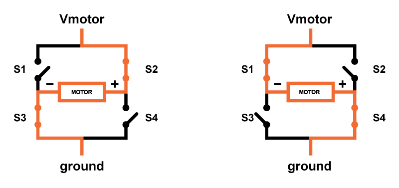
A fabricated H-bridge module is used for this tutorial. You can find a lot of schematics for H-bridge circuits in the web, but if you don't want to build you own, you can use a L298 IC.
Contact: John
Phone: +86-13631626001
E-mail: support@szbobet.com
Add: Longhua Area,Shenzhen City,China
 International
 Ali message