
By connecting an L298 bridge IC to an Arduino, you can control a DC motor.
A direct current, or DC, motor is the most common type of motor. DC motors normally have just two leads, one positive and one negative. If you connect these two leads directly to a battery, the motor will rotate. If you switch the leads, the motor will rotate in the opposite direction.
To control the direction of the spin of DC motor, without changing the way that the leads are connected, you can use a circuit called an H-Bridge. An H bridge is an electronic circuit that can drive the motor in both directions. H-bridges are used in many different applications, one of the most common being to control motors in robots. It is called an H-bridge because it uses four transistors connected in such a way that the schematic diagram looks like an "H."
You can use discrete transistors to make this circuit, but for this tutorial, we will be using the L298 H-Bridge IC. The L298 can control the speed and direction of DC motors and stepper motors and can control two motors simultaneously. Its current rating is 2A for each motor. At these currents, however, you will need to use heat sinks.
The pinouts for the L298 are shown below. You can find a datasheet the L298 at http://www.tech.dmu.ac.uk/~mgongora/Resources/L298N.pdf.
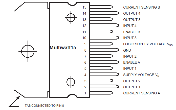
1 x L298 bridge IC
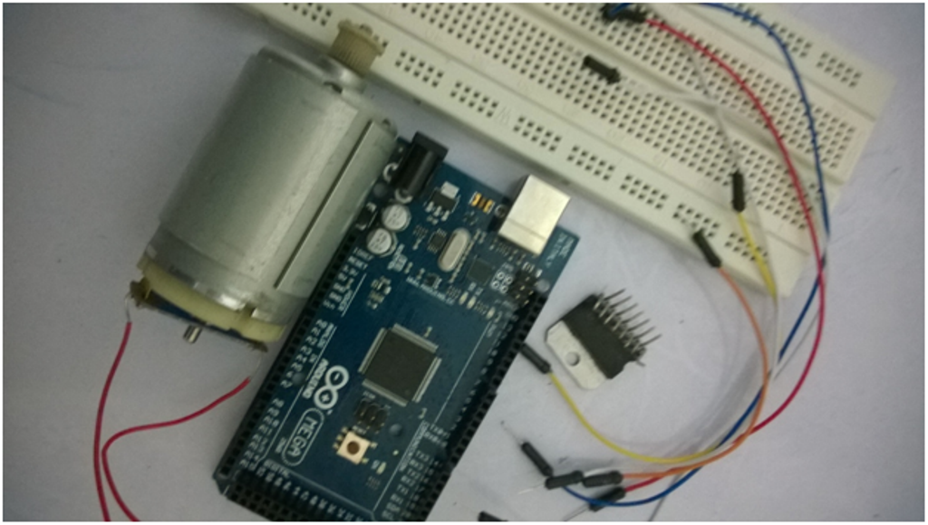
1 x DC motor
1 x Arduino Mega2560
1 x breadboard
10 x jumper wires
The schematic above shows how to connect the L298 IC to control two motors. There are three input pins for each motor, including Input1 (IN1), Input2 (IN2), and Enable1 (EN1) for Motor1 and Input3, Input4, and Enable2 for Motor2.
Since we will be controlling only one motor in this tutorial, we will connect the Arduino to IN1 (pin 5), IN2 (pin 7), and Enable1 (pin 6) of the L298 IC. Pins 5 and 7 are digital, i.e. ON or OFF inputs, while pin 6 needs a pulse-width modulated (PWM) signal to control the motor speed.
The following table shows which direction the motor will turn based on the digital values of IN1 and IN2.
| IN1 | IN2 | MOTOR |
|---|---|---|
| 0 | 0 | BRAKE |
| 1 | 0 | FORWARD |
| 0 | 1 | BACKWARD |
| 1 | 1 | BRAKE |
IN1 pin of the L298 IC is connected to pin 8 of the Arduino while IN2 is connected to pin 9. These two digital pins of Arduino control the direction of the motor. The EN A pin of IC is connected to the PWM pin 2 of Arduino. This will control the speed of the motor.
Contact: John
Phone: +86-13631626001
E-mail: support@szbobet.com
Add: Longhua Area,Shenzhen City,China
 International
 Ali message